Sunday 17 May 2020
Monday 20 August 2018
Sunday 10 September 2017
Concrete slump test is to determine the workability or consistency of concrete mix prepared at the laboratory or the construction site during the progress of the work. Concrete slump test is carried out from batch to batch to check the uniform quality of concrete during construction.
The slump test is the most simple workability test for concrete, involves low cost and provides immediate results. Due to this fact, it has been widely used for workability tests since 1922. The slump is carried out as per procedures mentioned in ASTM C143 in the United States, IS: 1199 – 1959 in India and EN 12350-2 in Europe.
Generally concrete slump value is used to find the workability, which indicates water-cement ratio, but there are various factors including properties of materials, mixing methods, dosage, admixtures etc. also affect the concrete slump value.
Factors which influence the concrete slump test:
- Material properties like chemistry, fineness, particle size distribution, moisture
content and temperature of cementitious materials. Size, texture, combined grading, cleanliness and moisture content of the aggregates, - Chemical admixtures dosage, type, combination, interaction, sequence of addition and its effectiveness,
- Air content of concrete,
- Concrete batching, mixing and transporting methods and equipment,
- Temperature of the concrete,
- Sampling of concrete, slump-testing technique and the condition of test equipment,
- The amount of free water in the concrete, and
- Time since mixing of concrete at the time of testing.
Equipments Required for Concrete Slump Test:
Mould for slump test, non porous base plate, measuring scale, temping rod. The mould for the test is in the form of the frustum of a cone having height 30 cm, bottom diameter 20 cm and top diameter 10 cm. The tamping rod is of steel 16 mm diameter and 60cm long and rounded at one end.
Sampling of Materials for Slump Test:
A concrete mix (M15 or other) by weight with suitable water/ cement ratio is prepaid in the laboratory similar to that explained in 5.9 and required for casting 6 cubes after conducting Slump test.
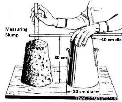
Figure-1: Measuring Slump of Concrete
Procedure for Concrete Slump Test:
- Clean the internal surface of the mould and apply oil.
- Place the mould on a smooth horizontal non- porous base plate.
- Fill the mould with the prepared concrete mix in 4 approximately equal layers.
- Tamp each layer with 25 strokes of the rounded end of the tamping rod in a uniform manner over the cross section of the mould. For the subsequent layers, the tamping should penetrate into the underlying layer.
- Remove the excess concrete and level the surface with a trowel.
- Clean away the mortar or water leaked out between the mould and the base plate.
- Raise the mould from the concrete immediately and slowly in vertical direction.
- Measure the slump as the difference between the height of the mould and that of height point of the specimen being tested.
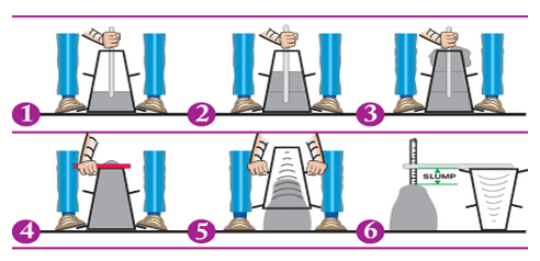
Figure-2: Concrete Slump Test Procedure
NOTE:
The above operation should be carried out at a place free from Vibrations or shock and within a period of 2 minutes after sampling.
Slump Value Observation:
The slump (Vertical settlement) measured shall be recorded in terms of millimeters of subsidence of the specimen during the test.
Results of Slump Test on Concrete:
Slump for the given sample= _____mm
When the slump test is carried out, following are the shape of the concrete slump that can be observed:
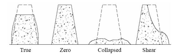
Figure-3: Types of Concrete Slump Test Results
- True Slump – True slump is the only slump that can be measured in the test. The measurement is taken between the top of the cone and the top of the concrete after the cone has been removed as shown in figure-1.
- Zero Slump – Zero slump is the indication of very low water-cement ratio, which results in dry mixes. These type of concrete is generally used for road construction.
- Collapsed Slump – This is an indication that the water-cement ratio is too high, i.e. concrete mix is too wet or it is a high workability mix, for which a slump test is not appropriate.
- Shear Slump – The shear slump indicates that the result is incomplete, and concrete to be retested.
CONSOLIDATION OF SOIL UNDER TIME-DEPENDANT LOADING AND VARYING PERMEABILITY
USE OF THE THEORY OF CONSOLIDATION IN MANY INSTANCES IS FOUND TO BE LESS THAN SATISFACTORY DUE TO THE WORKING CONDITIONS INHERENT IN THE USUAL THEORY. THIS PAPER EXTENDS THE THEORY BY GENERALIZING THE CONDITIONS OF DERIVATION TO INCLUDE VARIATIONS IN THE RATE OF LOADING AND VARIATIONS IN THE COEFFICIENT OF PERMEABILITY DURING THE PROCESS OF CONSOLIDATION. INCLUDING THE TWO ADDITIONAL WORKING CONDITIONS, THE BASIC DIFFERENTIAL EQUATION IS DERIVED IN ITS MOST GENERAL FORM. THE RESULTING DIFFERENTIAL EQUATION IS NON-LINEAR, BUT AN EXPONENTIAL APPROXIMATION IS DEVELOPED TO LINEARIZE IT, THEREBY PERMITTING SOLUTION OF THE CONSOLIDATION BOUNDARY VALUE PROBLEM. THE ONE-DIMENSIONAL CONSOLIDATION PROBLEM IS TREATED IN DETAIL FOR A CLAY-SOIL LAYER SANDWICHED BETWEEN TWO SAND LAYERS. A GENERAL SOLUTION IS PRESENTED FOR CONSTANT PERMEABILITY AND AN ARBITRARY LOADING RATE. SPECIFIC SOLUTIONS ARE PRESENTED FOR THE CONSOLIDATION DURING A LINEAR CONSTRUCTION PERIOD. WITH THESE SOLUTIONS, WORKING CURVES ARE PRESENTED FOR ACTUAL TIME COMPUTATIONS. IN ADDITION, THE THEORY OF VARIABLE PERMEABILITY IS DEVELOPED IN DETAIL IN TERMS OF SPECIFIC SOLUTIONS. THE CONSOLIDATION OF A DOUBLY-DRAINED LAYER OF CLAY-SOIL UNDER THE INFLUENCE OF TWO- AND THREE-DIMENSIONAL LOADING IS PRESENTED. THESE SOLUTIONS ARE DEVELOPED IN GENERAL, AND FOR SPECIFIC LINEAR LOADING FUNCTIONS, CONSIDERING CONSTANT PERMEABILITY. EXTENSIONS TO PROBLEMS OF VARIABLE PERMEABILITY ARE INDICATED. THE THREE-DIMENSIONAL CONSOLIDATION PROBLEM IS ALSO SPECIFICALLY ORIENTED TO THE RADIAL DRAINAGE OF A TRIAXIAL TEST SPECIMEN UNDER A STRESS- CONTROLLED LOADING. SAND-DRAIN PROBLEMS FOR EQUAL-STRAIN CONDITIONS AND RADIAL FLOW ONLY ARE COVERED IN DETAIL. THE EXACT SOLUTION TO CONSOLIDATION UNDER CONSTANT LOAD BUT VARIABLE PERMEABILITY IS PRESENTED IN TERMS OF THE WELL- KNOWN CONSTANT PERMEABILITY SOLUTION, WHICH CONSIDERS A PERFECT DRAIN WITHOUT SMEAR. CONSTANT PERMEABILITY SOLUTIONS ARE PRESENTED FOR THE CASE OF A LINEAR CONSTRUCTION LOADING, IN WHICH THE PRESENCE OF A SMEAR ZONE IS INCLUDED IN THE SOLUTION. THE EXPONENTIAL LINEARIZING APPROXIMATION IS DEVELOPED FOR SITUATIONS OF VARIABLE LOAD AND PERMEABILITY FOR THE CASE OF SAND DRAINS WITHOUT SMEAR. A SET OF WORKING CURVES IS PRESENTED FOR THE DESIGN OF SAND-DRAIN INSTALLATIONS USING THESE THEORIES
Thursday 7 September 2017
Residencial building Thumb rules
https://youtu.be/ZRiwXk0-XaQ
*Residencial building Thumb rules*
For Only Ground Floor Structure
Concrete Grade - M20
Column Size -230X230
Steel required for column
Vertical bar -12mm - 4 Nos
Stirrups @200c/c
Staircase with overhed water tank -
Column Size- 230X230
Vertical bar- 16mm - 4Nos
Stirrups @150mmC/C
Slab thick - 115 to125mm
Waist slab - 150 to 175 mm thick
Beam Width 230mm
Beam depth
For up to 3000mm span- 300mm
For 3000mm to 4500mm Span -450mm
For 4500 to 6000mm span -600mm
Steel required - 2.5 to 2.75Kg/Sqft
For G +1 Structure
Concrete Grade - M20
Column Size -300X300
Steel required for column
Vertical bar -12mm - 6Nos
Stirrups @200c/c
Staircase with overhed water tank -
Column Size- 300X300
Vertical bar- 16mm - 6Nos
Stirrups @150mmC/C
Slab thick - 115 to125mm
Waist slab - 150 to 175 mm thick
Beam Width 230mm
Beam depth
For up to 3000mm span- 300mm
For 3000mm to 4500mm Span -450
For 4500 to 6000mm span -600mm
Steel rewuired - 2.75 to 3.0Kg/Sqft
For G+2 Structure_
Concrete Grade - M20
Column Size -380X380
Steel required for column
Vertical bar -12mm - 8Nos
Stirrups @200c/c
Staircase with overhed water tank -
Column Size- 380X380
Vertical bar- 16mm - 6Nos
Stirrups @150mmC/C
Slab thick - 115 to125mm
Waist slab - 150 to 175 mm thick
Beam Width 230mm
Beam depth
For up to 3000mm span- 300mm
For 3000mm to 4500mm Span -450
For 4500 to 6000mm span -600mm
Steel required - 3.0 to 3.25Kg/Sqft
Sunday 3 September 2017
Following are the basic civil engineering tips you should be remembered while working on a construction site.
1. GRADE OF CONCRETE:
M5 – 1 : 4 : 8
M10 – 1 : 3 : 6
M15 – 1 : 2 : 4
M20 – 1 : 1.5 : 3
M25 – 1 : 1 : 2
2. CLEAR COVER TO MAIN REINFORCEMENT:
Footings : 50 mm
Raft Foundation (Top) : 50 mm
Raft Foundation (Bottom) : 75 mm
Raft Foundation (Side) : 75 mm
Beam : 25 mm
Strap Beam : 50 mm
Column :40 mm
Slab : 15 mm
flat Slab : 20 mm
Staircase : 15 mm
Retaining Wall : 20 – 25 mm
Water Retaining Structures : 2 0- 30 mm
Maximum water absorption by bricks – 20%
Compressive strength of common bricks – 3.5 N/mm2
Density Of Bricks- 1600-1920 Kg/m3
Minimum thickness of slab – 125 mm
Dimension tolerance for cubes – +2
Maximum free fall of concrete – 1.50 m
Lapping should not be used for the bars having larger dia than 36 mm.
Binding wire required for steel reinforcement – 8 kg per MT
3 samples should be taken for every 100 m2 in core cutting test.
Maximum chair spacing – 1 m.
Minimum dia should be used in dowels rod – 12 mm.
Hook for strriups (one side) – 9D
No. of strriups = (clear span/spanning) + 1
Length of main steel in cantilever anchorage – 69D.
Minimum no. of bars in square column – 4
Minimum no. of bars in circular column – 6
Minimum dia of main bars and distributors in the slab – 8 mm.
Maximum dia of main bars and distributors in the slab – 1/8 of slab thickness.
All reinforcement should be free from mill scales, loose rust, and coats of paints, oil or any other substances.
3. SETTING TIME:
Initial setting time should not be less than 30 minutes.
Final setting time should not be greater than 10 hours.
4. REQUIRED CURING DAYS:
Super sulfate cement – 7 days
Ordinary portland cement – 10 days
Cement with minerals and admixtures – 14 days.
5. SLUMP VALUE (IS-456):
Lightly reinforced concrete: 25 – 75 mm.
Heavily reinforced concrete: 75 – 100 mm.
Trench fill : 100 – 150 mm ( for in-situ & tremie).
6. CUBE SAMPLES:
1 – 5 m3 : 1 No.
6 – 15 m3 : 2 No..
16 – 30 m3 :3 No.
31 -50 m3 : 4 No.
Above 50 m3 : 4 + 1 no. of addition for each 50 m3.
Subscribe to:
Posts (Atom)

-
Concrete slump test is to determine the workability or consistency of concrete mix prepared at the laboratory or the construction site dur...
-
https://youtu.be/ZRiwXk0-XaQ *Residencial building Thumb rules* For Only Ground Floor Structure Concrete Grade - M20 Column Size -230X...


